The foil surface of the substrate is degreased. The panels skip thru a vacuum chamber in which a layer of fantastic photoresist material is pressed firmly onto the complete floor of the foil. A tremendous photoresist cloth is a polymer that has the assets of turning into extra soluble whilst uncovered to ultraviolet mild. HDI PCBs The vacuum ensures that no air bubbles are trapped between the foil and the photoresist. The published circuit pattern mask is laid on pinnacle of the photoresist and the panels are uncovered to an excessive ultraviolet light. Because the masks is clear within the regions of the published circuit sample, the photoresist in the ones areas is irradiated and will become very soluble.

7 The masks is removed, and the floor of the panels is sprayed with an alkaline developer that dissolves the irradiated photoresist in the areas of the printed circuit pattern, leaving the copper foil uncovered at the floor of the substrate.
Eight The panels are then electroplated with copper. The foil on the surface of the substrate acts as the cathode in this procedure, and the copper is plated inside the uncovered foil regions to a thickness of approximately zero.001-0.002 inches (zero.Half-zero.050 mm). The regions nonetheless covered with photoresist can’t act as a cathode and are not plated. Tin-lead or any other protective coating is plated on pinnacle of the copper plating to prevent the copper from oxidizing and as a face up to for the following manufacturing step.
Nine The photoresist is stripped from the forums with a solvent to reveal the substrate’s copper foil between the plated revealed circuit sample. The boards are sprayed with an acid solution which eats away the copper foil. The copper plating on the published circuit sample is included through the tin-lead coating and is unaffected with the aid of the acid.
Attaching the touch fingers
10 The touch palms are attached to the edge of the substrate to connect to the broadcast circuit. The touch palms are masked off from the rest of the board and then plated. Plating is executed with 3 metals: first tin-lead, subsequent nickel, then gold.
Fusing the tin-lead coating
11 The tin-lead coating on the surface of the copper published circuit sample could be very porous and is effortlessly oxidized. To protect it, the panels are passed through a “reflow” oven or warm oil tub which causes the tin-lead to soften, or reflow, into a glittery floor.
Sealing, stenciling, and slicing the panels
12 Each panel is sealed with epoxy to shield the circuits from being broken whilst additives are being connected. Instructions and other markings are stenciled onto the forums.
13 The panels are then reduce into individual forums and the edges are smoothed.
Mounting the additives
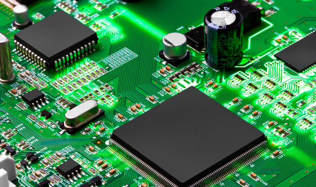
14 Individual forums skip thru several machines which region the electronic components of their right location inside the circuit. If floor mount generation goes for use to mount the additives, the forums first skip via an automated solder paster, which places a dab of solder paste at every element touch point. Very small components may be located by a “chip shooter” which swiftly locations, or shoots, the components onto the board. Larger additives may be automatically positioned. Some components may be too big or peculiar-sized for robotic placement and have to be manually placed and soldered later.